
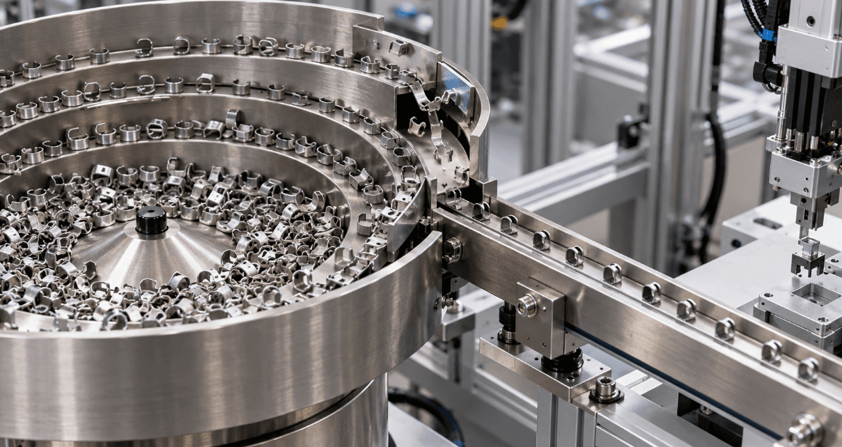
A clip that leaves the bowl correctly oriented can still turn sideways before reaching the assembly station. A thin stamped part may overlap its neighbor at the discharge or snag at the transition to a linear feeder. In both cases, the useful question is not simply whether the bowl vibrates. It is whether the whole feeding path can deliver individual parts in the required orientation at the required pace.
For asymmetric and thin walled components, feeder design starts with the actual part and ends at the handoff point. This guide explains where jams occur, what to assess in a custom vibratory bowl feeder, and how to test a proposed system before it joins a production line.
Contents
Why these parts are difficult to feed | How the feeding path controls orientation | Choosing and validating a system | Frequently asked questions
Why irregular parts jam even when the bowl is running
An asymmetric clip or bracket can rest in several positions. A cutout, longer leg or uneven mass distribution may make one orientation more stable during vibration, while the downstream machine requires another. As the part moves around the bowl, it can roll at a curve, lean against a guide, or turn when a restraint ends. The result may be a jam, an incorrectly presented part, or a missed pick.
Thin walled stampings introduce a different problem. Their edges may catch at a joint, and the parts may nest or overlap. Some are flexible enough to bend under a restrictive guide or an overly aggressive feed setting. Surface finish, burr direction, oil and dimensional variation can also change how nominally identical parts behave. A track proven with a single clean prototype may therefore behave differently with production batches.
Design the complete path from bulk parts to the handoff
Start with the bowl track and orientation features
A vibratory bowl feeder lifts parts along a spiral track. Custom tooling then retains the desired orientation and sends unwanted orientations back into the bowl. The right reject feature depends on what the part can reliably reveal: a long leg, a flange, a hole, an opening or an identifiable face. For a clip, a profile gauge or a carefully positioned rail may be useful; another part may need a change in track elevation or an air assist. These are design options to evaluate on samples, not features that every bowl requires.
The objective is to reject wrong positions early enough for the part to recirculate without obstructing the exit. Confirm that the reject feature still works when parts vary within their drawing tolerances. Also watch for double feeding: two thin pieces that overlap can appear to a simple guide like one thicker component.
Keep the orientation through the linear feeder
The bowl outlet is only one section of the system. Parts often travel along a straight vibratory track or linear feeder before a sensor, escapement or robot picks them up. The interface between the bowl and linear track can create a step, sudden change in width or unsupported edge. Any of these can undo the orientation achieved inside the bowl.
A controlled transfer should accommodate the real part envelope and give it a stable bearing surface. The guide must be open enough for acceptable variation and close enough to limit unwanted rotation or stacking. There is no universal clearance or chamfer angle for thin parts: both depend on wall stiffness, burrs, coating, allowable contact and feed speed. Review the full path at normal operating conditions, including the last part at the discharge.
Match the discharge to the assembly machine
A feeder that produces a high flow of parts may still cause stoppages if the machine cannot accept them consistently. Define whether the downstream process needs single parts at a fixed pitch, a buffered queue or individually released components. An escapement can separate the leading part for a pick and place device, while sensors can indicate low level, presence or a blocked track. Agree on the presentation position and orientation with the machine integrator before fixing the outlet design.
Select the feeding approach around the actual component
A custom stainless steel vibratory bowl feeder is a sensible starting point when one part type runs for long periods and mechanical orientation can be achieved repeatably. Hongchao lists bowl feeders designed for clips, including a multi lane model, as well as linear drives and controllers that can form part of the delivery path. Those listings establish the relevant product scope; the published feed rate of one clip feeder should not be treated as a guaranteed rate for a different part. Each new geometry needs its own trial.
For very small parts, the company also lists a CNC vibratory bowl feeder category. When part designs change often or mechanical orientation would need extensive tooling, its flexible feeder category may be worth assessing. The choice depends on the needed output orientation, changeover frequency, available floor space and how the downstream station identifies or picks parts.
What to send the feeder supplier and what to verify
Provide a drawing with the dimensions that affect orientation, several batches of physical parts, and photographs of acceptable and unacceptable presentation. Include material, wall thickness, burr direction, surface treatment and whether parts arrive oily or tangled. Explain the required output rate in accepted parts per minute, the handoff position, available utilities and space, and what the line does when it stops or restarts.
Ask for a trial using production representative samples, including the small and large ends of the permitted dimensional range. Observe the bowl, reject points, linear track and discharge separately. Record accepted output, wrong orientation, double feeds, jams and visible damage over an agreed test duration. A short run at peak speed can expose immediate faults; a longer run also tests accumulation, wear sensitivity and the behavior of varying fill levels. Define the acceptance criteria with the supplier before the trial rather than relying on a general claim of jam free feeding.
Frequently asked questions
Can vibration speed alone solve a jamming problem
Sometimes a controller adjustment improves flow, but it will not correct a part that can rotate freely at a transition or two pieces that overlap in a guide. First locate where the interruption starts; then adjust the relevant geometry or operating setting and repeat the trial.
Should every thin part use a very narrow track gap
No. A gap that prevents overlap in one design may bend another part or trap a burr. Set clearances from measured production samples and confirm that the part remains undamaged at the required output rate.
Can an existing bowl feeder be modified
Possibly. If the bowl has sufficient capacity and the fault is confined to an orientation feature, transition or discharge, revised tooling may help. Changes to the part geometry, feed rate or pick position can make a new bowl or delivery layout more practical. Inspect the existing system and test both options with real parts.
Conclusion
Feeding asymmetric and thin walled parts reliably requires more than a smooth bowl surface. The orienting features, straight track and final handoff must work as one path. Define the desired presentation, examine the full range of production parts, and validate the complete system at the line’s operating conditions. That gives buyers a useful basis for specifying a custom vibratory bowl feeder and judging whether it is ready for production.